Add-ons and more

Raytracing concepts and code, part 11, antialiasing


This is an article in a multipart series on the concepts of ray tracing. I am not sure where this will lead but I am open to suggestions. We will be creating code that will run inside Blender. Blender has ray tracing renderers of course but that is not the point: by reusing Python libraries and Blender's scene building capabilities we can concentrate on true ray tracing issues like shader models, lighting, etc.
I generally present stuff in a back-to-front manner: first an article with some (well commented) code and images of the results, then one or more articles discussing the concepts. The idea is that this encourages you to experiment and have a look at the code yourself before being introduced to theory. How well this works out we will see :-)

So far the series consists of the several articles labeled ray tracing concepts

Anti aliasing

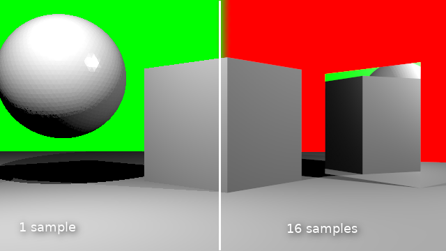
If we want to diminish the jagged look of edges in our rendered image we can sample a pixel multiple times at slightly different positions and average the result. In this article I show the code to do this.

Code

Once we know how many times we want to sample a pixel we have to calculate our camera ray as many times but with slightly shifted coordinates and then average the result. If we take the original direction of the camera ray to point into the exact middle of an on screen pixel, we have pick a point in the square centered around this point.
For this we first calculate the size of this square (line 9 and 10). Then as before we calculate each pixel but we repeat this for every sample (line 14). We keep the sum of all our samples in a separate buffer sbuf (defined in line 5, the addition is in line 23). We still want the final buffer that will be shown on screen to represent the averaged color we calculated so far, so in line 15 we update a whole line of pixels to represent the current average.
We also invert the line above it (line 16,17) so we have some visual feedback of where we are when we are updating the buffer. This is useful to keep track as with increasing samples the contribition gets smaller and might be hardto see.
Finally we yield the percentage of samples we calculated so far.
Note that the vdc() function returns a number from a Van der Corput sequence. I have not shown this function and you could use uniformly distributed random numbers instead (shown in the line that is commented out) in stead of these quasi random numbers, but these should give better results. The reasoning behind this is out of scope of this article but check Wikipedia for more on this.
def ray_trace(scene, width, height, depth, buf, samples, gi):     

    ... indentical code left out ...

    sbuf = np.zeros(width*height*4)
    sbuf.shape = height,width,4

    aspectratio = height/width
    dy = aspectratio/height
    dx = 1/width
    seed(42)

    N = samples*width*height
    for s in range(samples):
        for y in range(height):
            yscreen = ((y-(height/2))/height) * aspectratio
            for x in range(width):
                xscreen = (x-(width/2))/width
                #dir = Vector((xscreen + dx*(random()-0.5), yscreen + dy*(random()-0.5), -1))
                dir = Vector((xscreen + dx*(vdc(s,2)-0.5), yscreen + dy*(vdc(s,3)-0.5), -1))
                dir.rotate(rotation)
                dir = dir.normalized()
                sbuf[y,x,0:3] += single_ray(scene, origin, dir, lamps, depth, gi)
            buf[y,:,0:3] = sbuf[y,:,0:3] / (s+1)
            if y < height-1:
                buf[y+1,:,0:3] = 1 - buf[y+1,:,0:3]
            yield (s*width*height+width*y)/N
When we call our new ray_trace() function we have to determine the number of samples first. Blender provides two properties from the render context for this: scene.render.use_antialiasing and scene.render.antialiasing_samples. For some reason that last one is a string, so we have to convert it to an int before we can use it:
    def render_scene(self, scene):

    ... indentical code left out ...

        samples = int(scene.render.antialiasing_samples) if scene.render.use_antialiasing else 1
        for p in ray_trace(scene, width, height, 1, buf, samples, gi):

    ... indentical code left out ...

Now we could make the whole existing anti-aliasing panel available by again adding our engine to the COMPAT_ENGINES attribute but because it had lots of options we don't use we create our own panel with just the properties we need (something we might do later for other panels as well):
from bpy.types import Panel
from bl_ui.properties_render import RenderButtonsPanel

class CUSTOM_RENDER_PT_antialiasing(RenderButtonsPanel, Panel):
    bl_label = "Anti-Aliasing"
    COMPAT_ENGINES = {CustomRenderEngine.bl_idname}

    def draw_header(self, context):
        rd = context.scene.render

        self.layout.prop(rd, "use_antialiasing", text="")

    def draw(self, context):
        layout = self.layout

        rd = context.scene.render
        layout.active = rd.use_antialiasing

        split = layout.split()

        col = split.column()
        col.row().prop(rd, "antialiasing_samples", expand=True)

Code availability

The revision containing the code changes from this article is available from GitHub.


Raytracing concepts and code, part 10, showing progress


This is an article in a multipart series on the concepts of ray tracing. I am not sure where this will lead but I am open to suggestions. We will be creating code that will run inside Blender. Blender has ray tracing renderers of course but that is not the point: by reusing Python libraries and Blender's scene building capabilities we can concentrate on true ray tracing issues like shader models, lighting, etc.
I generally present stuff in a back-to-front manner: first an article with some (well commented) code and images of the results, then one or more articles discussing the concepts. The idea is that this encourages you to experiment and have a look at the code yourself before being introduced to theory. How well this works out we will see :-)

So far the series consists of the several articles labeled ray tracing concepts

Progress

The bits of code we show in this article have less to do with raytracing per se but do show off the options to indicate progress in Blender's RenderEngine class. Not only gives this some visual feedback when rendering takes long, it also gives the user the opportunity to cancel the process in mid-render.

Code

First we change the ray_trace() function into a generator that returns the y-coordinate after every line. This is accomplished by the yield statement. So now the function doesn't allocate a buffer itself but it takes a buf argument.
def ray_trace(scene, width, height, depth, buf):     

    ... identical code left out ...

    for y in range(height):
        yscreen = ((y-(height/2))/height) * aspectratio
        for x in range(width):
            xscreen = (x-(width/2))/width

            ... identical code left out ...            

        yield y
The render_scene() is changed too: it allocates a suitable buffer and then iterates over every line in the render result as it gets rendered (line 9). It then calls the update_result() function of RenderEngine class to show on screen what is rendered so far (line 12). It also calculates the percentage that has been completed and signals that as well (line 14).
    def render_scene(self, scene):
        height, width = self.size_y, self.size_x
        buf = np.ones(width*height*4)
        buf.shape = height,width,4
        
        result = self.begin_result(0, 0, self.size_x, self.size_y)
        layer = result.layers[0].passes["Combined"]
        
        for y in ray_trace(scene, width, height, 1, buf):
            buf.shape = -1,4
            layer.rect = buf.tolist()
            self.update_result(result)
            buf.shape = height,width,4
            self.update_progress(y/height)
        
        self.end_result(result)

Code availability

The code for this article is available in this revision on GitHub. (Note that it already contains some none functional global illumination code that you can ignore).

Raytracing concepts and code, part 9, adding a background image


This is an article in a multipart series on the concepts of ray tracing. I am not sure where this will lead but I am open to suggestions. We will be creating code that will run inside Blender. Blender has ray tracing renderers of course but that is not the point: by reusing Python libraries and Blender's scene building capabilities we can concentrate on true ray tracing issues like shader models, lighting, etc.
I generally present stuff in a back-to-front manner: first an article with some (well commented) code and images of the results, then one or more articles discussing the concepts. The idea is that this encourages you to experiment and have a look at the code yourself before being introduced to theory. How well this works out we will see :-)

So far the series consists of the several articles labeled ray tracing concepts

When a ray does not hit anything we would like it to intersect with some infinite spherical background.

In Blender it is quite easy to associate a texture with the world background which is used by Blender Internal (but not Cycles which uses node based world settings exclusively):


(The important bit when creating a new texture is select World texture and of course an appropriate mapping for the image. [here we use an image from HDRIHaven])

The ray tracing renderer that we are writing will make use of this texture for the background image as well as for some environment lighting (more on this in a future article)

Elevation and azimuth

Any image texture object offers an evaluate() function that will take two arguments x and y between [-1,1] and will return the color at that point. The point (0,0) will be exactly in the middle of the regardless of its dimensions.

If we assume this image covers the whole <em>skydome</em>, this means that all we have to do when a ray doesn't hit anything in the scene, is to find out how high above (or below) the horizon the ray is pointing and in what direction along the horizon.

The first item is called the elevation (or altitude) and ranges from -90° (or -pi/2 , pointing straight down) to +90° (+pi/2, i.e. straight up).

The second item is called the azimuth and ranges from -180° (-pi) to +180° (+pi) relative to some fixed direction. We will use the positive x-axis as our reference.

Given a normalized direction in cartesian (x,y,z) coordinates, finding the elevation (theta) and azimuth (phi) is pretty straightforward.

Code


Calculating theta and phi and mapping them to [-1,1] is shown in the code below:

    elif scene.world.active_texture:
        theta = 1-acos(dir.z)/pi
        phi = atan2(dir.y, dir.x)/pi
        color = np.array(scene.world.active_texture.evaluate(
                                     (-phi,2*theta-1,0)).xyz)

Because the dir vector is normalized the z component will give us the cosine of the angle between the vector and the z-axis. The conversions are necessary to relate this angle (theta) to the horizontal plane and scale it to [-1,1]. The angle phi is calculated relative to the positive x-axis. The color we get pack from the evaluate call may contain an alpha channel therefore we make sure we only keep the first three components with the .xyz attribute.
The code is available on GitHub. It also contains the necessary code to  show a panel with options to associate a background texture with a World (it reuses a panel from Blender's internal renderer)


Raytracing concepts and code, part 8, mirror reflections


This is an article in a multipart series on the concepts of ray tracing. I am not sure where this will lead but I am open to suggestions. We will be creating code that will run inside Blender. Blender has ray tracing renderers of course but that is not the point: by reusing Python libraries and Blender's scene building capabilities we can concentrate on true ray tracing issues like shader models, lighting, etc.
I generally present stuff in a back-to-front manner: first an article with some (well commented) code and images of the results, then one or more articles discussing the concepts. The idea is that this encourages you to experiment and have a look at the code yourself before being introduced to theory. How well this works out we will see :-)

So far the series consists of the several articles labeled ray tracing concepts

Mirror reflections

Mirror reflections are an important part of ray traced images. Many materials like glass and metals have a reflective component. Calculating ray traced reflections is surprisingly simple as we will see but we do need some options from the material properties so that we can specify whether a material has mirror reflectivity at all and what amount. Again we borrow an existing panel (and ignore most options present; later we will create our own panels with just the options we need but cleanup is not in focus just yet)


Reflecting a ray

To calculate mirror reflection we take the incoming ray from the camera and calculate the new direction the ray will take after the bounce and see if it hits anything. The direction of the reflected ray depends on the direction of the incoming ray and the surface normal: the angle between the normal and the incoming ray equals the angle between the normal and the reflected ray:

If the the length of all vectors are normalized, we can calculate the reflected ray using this expresion: dir - 2 * normal * dir.dot(normal)
For a more in depth explanation you might want to take a look at Paul Bourke's site.

Code

To deal with mirror reflecting the single_ray() function needs a small enhancement: it needs to check the amount of mirror reflectivity specified in the material (if any) and then, if the number of bounces we made is still less than the specified depth, calculated the reflected ray and use this new direction to cast a new ray and see if it hits something:
        ... identical code left out ...

        mirror_reflectivity = 0
        if len(mat_slots):
            mat = mat_slots[0].material
            diffuse_color = mat.diffuse_color * mat.diffuse_intensity
            specular_color = mat.specular_color * mat.specular_intensity
            hardness = mat.specular_hardness
            if mat.raytrace_mirror.use:
                mirror_reflectivity = mat.raytrace_mirror.reflect_factor

        ...

        if depth > 0 and mirror_reflectivity > 0:
            reflection_dir = (dir - 2 * normal  * dir.dot(normal)).normalized()
            color += mirror_reflectivity * single_ray(
                       scene, loc + normal*eps, reflection_dir, lamps, depth-1)

        ...

Code availability

The code for this revision is available from GitHub.

Raytracing concepts and code, part 7, colored lights and refactored ray cast


This is an article in a multipart series on the concepts of ray tracing. I am not sure where this will lead but I am open to suggestions. We will be creating code that will run inside Blender. Blender has ray tracing renderers of course but that is not the point: by reusing Python libraries and Blender's scene building capabilities we can concentrate on true ray tracing issues like shader models, lighting, etc.
I generally present stuff in a back-to-front manner: first an article with some (well commented) code and images of the results, then one or more articles discussing the concepts. The idea is that this encourages you to experiment and have a look at the code yourself before being introduced to theory. How well this works out we will see :-)

So far the series consists of the several articles labeled ray tracing concepts

Refactoring

To make it easier to caculate secondary rays like relected or refracted rays, we move the actual ray casting to its own function, which also makes the central loop that generates every pixel on the screen much more readable:
    for y in range(height):
        yscreen = ((y-(height/2))/height) * aspectratio
        for x in range(width):
            xscreen = (x-(width/2))/width
            # align the look_at direction
            dir = Vector((xscreen, yscreen, -1))
            dir.rotate(rotation)
            dir = dir.normalized()
            buf[y,x,0:3] = single_ray(scene, origin, dir, lamps, depth)

Colored lights

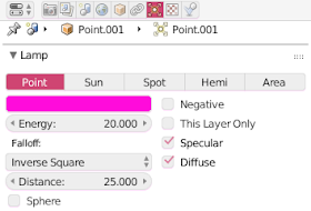
Within the single_ray() function we also add a small enhancement: now we calculate the available amount of light to use in reflections from the properties in the lamp data:
        ...
        for lamp in lamps:
            light = np.array(lamp.data.color * lamp.data.energy)
        ...

User interface

To allow the user to set the color and intensity ("energy") of the point lights we need the corresponding lamp properties panel (we only use color and energy):

This panel is added in the register() function:
    from bl_ui import (
            properties_render,
            properties_material,
            properties_data_lamp,
            )

    ... identical code left out ...

    properties_data_lamp.DATA_PT_lamp.COMPAT_ENGINES.add(CustomRenderEngine.bl_idname)

Code availability

This revision of the code is available from GitHub

Raytracing concepts and code, part 6, specular reflection for lights


This is an article in a multipart series on the concepts of ray tracing. I am not sure where this will lead but I am open to suggestions. We will be creating code that will run inside Blender. Blender has ray tracing renderers of course but that is not the point: by reusing Python libraries and Blender's scene building capabilities we can concentrate on true ray tracing issues like shader models, lighting, etc.
I generally present stuff in a back-to-front manner: first an article with some (well commented) code and images of the results, then one or more articles discussing the concepts. The idea is that this encourages you to experiment and have a look at the code yourself before being introduced to theory. How well this works out we will see :-)

So far the series consists of the several articles labeled ray tracing concepts
Until now the reflections have been a bit dull because our shader model only takes into account the diffuse reflectance, so lets take a look at how we can add specular reflectance to our shader.
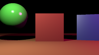
The effect we want to achieve is illustrated in the two images below where the green sphere on the right had some specular reflectance. Because of this it shows highlights for the two points lamps that are present in the scene.


The icosphere shows faceting because we did not yet anything to implement smooth shading (i.e. interpolating the normals across a face) but with added some smooth subdivisions to show off the high lights a bit better.
In the image below we see that we also look at the hardness of the specular reflections in our shader model, with a high value of 400 giving much tighter highlights than the default hardness of 50.


In both images the red cube has no specular intensity and the blue one has a specular intensity of .15 and a hardness of 50.

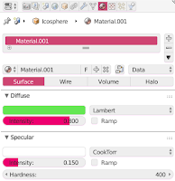
Specular color, specular intensity and hardness are properties of a material so we have also exposed the relevant panel to our custom renderer so that the user can set these values.

Code

The code changes needed in the inner shading loop of our ray tracer are limited:
if hit:
 diffuse_color = Vector((0.8, 0.8, 0.8))
 specular_color = Vector((0.2, 0.2, 0.2))
 mat_slots = ob.material_slots
 hardness = 0
 if len(mat_slots):
  diffuse_color = mat_slots[0].material.diffuse_color \
                    * mat_slots[0].material.diffuse_intensity
  specular_color = mat_slots[0].material.specular_color \
                    * mat_slots[0].material.specular_intensity
  hardness = mat_slots[0].material.specular_hardness

  ... identical code left out ...
  
  if not lhit:
   illumination = light * normal.dot(light_dir)/light_dist
   color += np.array(diffuse_color) * illumination
   if hardness > 0:  # phong reflection model
    half = (light_dir - dir).normalized()
    reflection = light * half.dot(normal) ** hardness
    color += np.array(specular_color) * reflection
We set reasonable defaults (line 2 - 5), override those defaults if we have a material on this object (line 6 - 11) and then, if we are not in the shadow, calculate the diffuse component of the lighting as before (line 16 - 17) and the finally add a specular component (line 18 - 21)

For the specular component we use the Phong model (or actually the Blinn-Phong model). This means we look at the angle between the normal (shown in light blue in the image below) and the half way vector (in dark blue). The smaller the angle the tighter the highlight. The tightness is controlled by the hardness: we raise the cosine of the angle (which is what the dot product is that we compute in line 20) to the power of this hardness. Note that the half way vector is the normalized vector that points exactly in between the direction of the light and the camera as seen from the point being shaded. That is why we have a minus sign rather than a plus sign in line 19 because dir in our code points from the camera towards the point being shaded.

Code availability

The code is available on GitHub.

Raytracing concepts and code, part 5, diffuse color


This is an article in a multipart series on the concepts of ray tracing. I am not sure where this will lead but I am open to suggestions. We will be creating code that will run inside Blender. Blender has ray tracing renderers of course but that is not the point: by reusing Python libraries and Blender's scene building capabilities we can concentrate on true ray tracing issues like shader models, lighting, etc.
I generally present stuff in a back-to-front manner: first an article with some (well commented) code and images of the results, then one or more articles discussing the concepts. The idea is that this encourages you to experiment and have a look at the code yourself before being introduced to theory. How well this works out we will see :-)

So far the series consists of the several articles labeled ray tracing concepts

Our rendered scene so far mainly consists of fifty shades of gray and that might be exciting enough for some but it would be better if we could spice it up with some color.

For this we will use the diffuse color of the first material slot of an object (if any). The code so far needs very little change to make this happen:
            # the default background is black for now
            color = np.zeros(3)
            if hit:
                # the get the diffuse color of the object we hit
                diffuse_color = Vector((0.8, 0.8, 0.8))
                mat_slots = ob.material_slots
                if len(mat_slots):
                    diffuse_color = mat_slots[0].material.diffuse_color
                        
                color = np.zeros(3)
                light = np.ones(3) * intensity  # light color is white
                for lamp in lamps:
                    # for every lamp determine the direction and distance
                    light_vec = lamp.location - loc
                    light_dist = light_vec.length_squared
                    light_dir = light_vec.normalized()
                    
                    # cast a ray in the direction of the light starting
                    # at the original hit location
                    lhit, lloc, lnormal, lindex, lob, lmat = scene.ray_cast(loc+light_dir*eps, light_dir)
                    
                    # if we hit something we are in the shadow of the light
                    if not lhit:
                        # otherwise we add the distance attenuated intensity
                        # we calculate diffuse reflectance with a pure 
                        # lambertian model
                        # https://en.wikipedia.org/wiki/Lambertian_reflectance
                        color += diffuse_color * intensity * normal.dot(light_dir)/light_dist
            buf[y,x,0:3] = color
In lines 5-8 we check if there is at least one material slot on the object we hit and get its diffuse color. If there is no associated material we keep a default light grey color.
This diffuse color is what we use in line 28 if we are not in the shadow.

Code availability

The code is available on GitHub.

Raytracing: concepts and code, part 4, the active camera


This is an article in a multipart series on the concepts of ray tracing. I am not sure where this will lead but I am open to suggestions. We will be creating code that will run inside Blender. Blender has ray tracing renderers of course but that is not the point: by reusing Python libraries and Blender's scene building capabilities we can concentrate on true ray tracing issues like shader models, lighting, etc.
I generally present stuff in a back-to-front manner: first an article with some (well commented) code and images of the results, then one or more articles discussing the concepts. The idea is that this encourages you to experiment and have a look at the code yourself before being introduced to theory. How well this works out we will see :-)

So far the series consists of the several articles labeled ray tracing concepts

In a further bit of code cleanup we'd like to get rid of the hardcoded camera position and look at direction by using the location of the active camera in the scene together with its rotation.
Fortunately very little code has to change to make this happen in our render method:

    # the location and orientation of the active camera
    origin = scene.camera.location
    rotation = scene.camera.rotation_euler
Using the rotation we can first create the camera ray as if it originated in the default -Z direction and then simply rotate it using the camera location:
    aspectratio = height/width
    # loop over all pixels once (no multisampling)
    for y in range(height):
        yscreen = ((y-(height/2))/height) * aspectratio
        for x in range(width):
            xscreen = (x-(width/2))/width
            # align the look_at direction
            dir = Vector((xscreen, yscreen, -1))
            dir.rotate(rotation)
Later we might even adapt this code to take into account the field of vision, but for now at least we can position and aim the active camera in the scene any way we like.

Code availability

The code is available on GitHub.