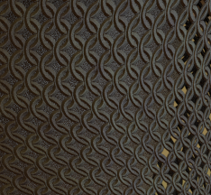
If you want to know more about chainmail patterns, both historical and contemporary ones, you might like to visit artofchainmail.com or cgmaille.com.
In the picture ob the left I used the chainmail shader to generate the pattern on the neck flap. The picture was created with a wood texture from cgtextures.com for the table top but all other textures are procedural. The scene was lit using the Prov-Wash HDRI maps by Alex Hart as found on hdrlabs.com. I think it is a kind of museum and that fits the helmet setting nicely.
Like the barbwire and chainlink shaders the shader presented in this article is again essentially nothing more than a simple black and white pattern with the distance to the center of the line added as a feature to aid in generating bumps. The difficulty here is to get all those overlaps correct as can be seen in the enlarged cut out selection shown on the right.
#include "stdosl.h"

int between(float v, float a, float b){ return v >= a && v <= b; }
float arc(float r, float a, float b) { return sqrt(0.5-abs(0.5-((r-a)/(b-a)))); }
float rmap(float a, float b, float ra[3] ){
 if ( between(ra[0], a, b) ) { return ra[0]; }
 if ( between(ra[1], a, b) ) { return ra[1]; }
 if ( between(ra[2], a, b) ) { return ra[2]; }
 return -1;
}

float basepattern(float r1, float r2, float r3, int fx, int fy, float Rm, float Rp){
 float x0y0[3] = {r3, r1, r2};
 float x0y1[3] = {r2, r3, r1};
 float x1y0[3] = {r1, r3, r2};
 float x1y1[3] = {r2, r1, r3};

 float r = -1;
 if ( fx ){
  if ( fy ) {
   r = rmap(Rm, Rp, x1y1);
  } else {
   r = rmap(Rm, Rp, x1y0);
  }

 } else {
  if ( fy ) {
   r = rmap(Rm, Rp, x0y1);
  } else {
   r = rmap(Rm, Rp, x0y0);
  }
 }
 return r;
}

shader chainmail4in1 (
 point Pos = P,
 float Scale = 1,
 float Radius = 0.47,
 float Width = 0.08,
 output float Fac = 0,
 output float Disp = 0
){
 point p = Pos * Scale ;
 float x = mod(p[0],1);
 float y = mod(p[1],1);

 float Rm = Radius - Width;
 float Rp = Radius + Width;

 float r=-1,r1,r2,r3,cr1,cr2,cr3;

 int fx = 0, fy = 0 , flip = y > x, flipt = y > ( 1 - x );
 if ( x > 0.5 ){ x = 1 - x ; fx = 1; }
 if ( y > 0.5 ){ y = 1 - y ; fy = 1; }

 r1 = hypot(x-0.5,y-0.5);
 r2 = hypot(x-0.5,y+0.5);
 r3 = hypot(x+0.5,y-0.5);

 float xc = mod(p[0]+0.5,1);
 float yc = mod(p[1]+0.5,1);

 int fxc = 0, fyc = 0, flipc = y > x;

 if ( xc > 0.5 ){ xc = 1 - xc ; fxc = 1; }
 if ( yc > 0.5 ){ yc = 1 - yc ; fyc = 1; }

 cr1 = hypot(xc-0.5,yc-0.5);
 cr2 = hypot(xc-0.5,yc+0.5);
 cr3 = hypot(xc+0.5,yc-0.5);

 if ( flip ^ flipt ){
  // base pattern
  r = basepattern(r1,r2,r3,fx,fy,Rm,Rp);
  if ( r> -1){
   Fac = 1;
   Disp = arc(r,Rm,Rp);
  } else {
   // connecting rings
   r = basepattern(cr1,cr2,cr3,fxc,fyc,Rm,Rp);
   if ( r> -1){
    Fac = 1;
    Disp = arc(r,Rm,Rp);
   }
  }
 } else {
  // connecting rings
  r = basepattern(cr1,cr2,cr3,fxc,fyc,Rm,Rp);
  if ( r> -1){
   Fac = 1;
   Disp = arc(r,Rm,Rp);
  } else {
   // base patterm
   r = basepattern(r1,r2,r3,fx,fy,Rm,Rp);
   if ( r> -1){
    Fac = 1;
    Disp = arc(r,Rm,Rp);
   }
  }
 }
}
The trick is to see that the pattern is very symmetrical. Each quadrant is basically the aame and consists of two quarter ring segments, one centered on the center of the square we are filling, the other one on the corner. The whole business of which to test for in what order is done to make sure that we know which ring segment is on top so that we can calculate a displacement correctly. It is all a bit too complicated to explain and in fact the code was created on a trial and error basis :-) It is however quite simple to use and that's why I share it of course :-) Example node setup
Like most of the shaders I present on this blog the pattern probably is easiest to work with on an uv-mapped object. In the picture of the helmet the neckflap is just that, a curved, subdivided square that is uv-mapped with simple unwrapping. The node setup is shown below.The green part is where we switch between a fully transparent shader or a metal shader based on the ouput of our script node. The diffuse part of the metal shader is given some color variation by the noise generated in the red box. The blue box s where we perturb our uv-coordinates a little bit adding a small amount of color noise in order to make our chainmail pattern a little less regular.


No comments:
Post a Comment