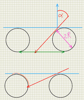
Fibers are generally not square. Their cross section more often approximates a circle. This does affect the occlusion a little bit because unlike a square the apparent cross section does not change with the angle of incidence. This means that we can approximate the transmission factor the apparent surface minus the diameter of the fiber as shown in the diagram below:

If the angle of incidence
α is so large that cos(α) < 2r there will be no transmission at all. So far this doesn't differ that much from a square cross section, however there is another phenomenon that we want to model: the sharpness of the specular reflection changes with the angle of incidence.
This happens once the angle of incidence is so large that the fiber start to occlude each other. As the occlusion increases, we see effectively a smaller segment of a circle (orange arc in left circlebin lower part of the diagram) and therefore we see less different normals. As we approach a grazing angle we effectively see just the top of the circle with normals nearly identical to the surface normal. It can be shown that the size of the circle segment we see is proportional to the angle of incidence as well.
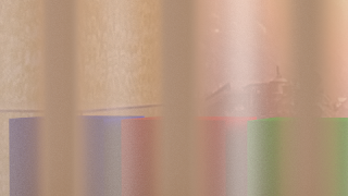
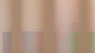
If we compare the old and the new shader the result looks quite different:

The old equation

With new equation
Code and example node setup
The code is rather self explanatory:
shader sheet_occlusion2 (
  normal Normal=N,
  float Radius=0.05,

  output float Fac=1,
  output float Var=1
){
  // calculate angle of incidence
  float alpha = acos(dot(I,Normal));
  // treat front and back the same
  alpha = alpha > M_PI_2 ? M_PI - alpha : alpha;
  // calculate the non occluded fraction
  Fac = cos(alpha) - 2 * Radius;
  // calculate the range of the visible normals
  if( Fac < 0 ){
    Fac = 0;
    Var = cos(alpha) / (2 * Radius);
  }
}
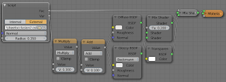
And the sample node setup mixes transparent shader with a non transparent shader just like before but uses the Var output to modify the shininess of the non transparent shader:
No comments:
Post a Comment