Showing posts with label wood shader. Show all posts

Sample artwork with ProWood shaders

I started playing around with Karl Andreas Gross' ProWood Shader pack and after some twiddling around I must say I like it:

In this example scene (a scene from Chocofur) I used the beech preset material for the chair (the chair is also from Chocofur. Note that I dropped the bundled textured material and replaced it by the ProWood procedural material). I picked the colors to match and upped the brightness and the reflectivity a bit to get the varnished look of the steam-pressed plywood of the chair. The books were generated by the book wizard cover generator.

For the floor (generated with my floorboard add-on) I used the material preset that is included in the shader pack specifically for the add-on, in this case oak. I just changed the colors. I had to changed the profile in bevel settings of the floor to 0.69 to prevent strange shadows. That has nothing to do with the shaders but everything with the geometry of the planks my add-on is generating, so it might be a good idea to make this the default in future versions.

floorboard add-on: a commercial shader with specific support

My free floorboards add-on has proven to be quite popular and now even a professional shader writer, Karl Andreas Groß, has created a wood shader collection that includes specific settings for use with the add-on. His shaders are available on BlenderMarket and I hope to try them out myself soon.

The floorboard add-on itself can be downloaded from GitHub.

Generate floor boards quick and easy, part VI

This version (0.0.8) of the floor board generator adds options to add twists and hollow curvature to the individual planks. This is useful when creating floors in older houses and its more subtle simply rotation planks. All the options are now visually grouped as well to aid the user in locating related options.


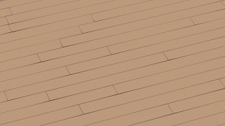
An example (with a flat material to emphasize the subtle curvature) is shown below (click to enlarge):

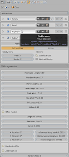
The option values used to create the image are shown in the next image. Note that for illustrative purposes we made the gaps between the planks quite large:

Parameterization

The biggest change in this version was already visible in the image above: parameters no longer appear in the toolbar but in the FloorBoards section of the modifier options. This is not only a visual change but it actually means that even after savinf the .blend file all relevant parameters are retained along with the abject and can be tweaked at any time. (Thanks floric for the code adaptation and DragonLEE for the original idea)

Generate floor boards quick and easy, part V

This version (0.0.7) of the floor board generator adds options to add small random rotations to the individual planks. This is useful when creating floors in older houses. All the options are now visually grouped as well to aid the user in locating related options.

An example (with exaggerated values for the rotations) is shown below (click to enlarge):

The option values used to create the image are shown in the next image. Note that for illustrative purposes we made the gaps between the planks and the random rotation values quite large:

Generate floor boards quick and easy, part III, vertex colors

A member at BlenderArtists really wanted to apply a random material to each individual plank. Now Cycles can generate a unique random number for each object but not for each face within an object so another trick was needed. I therefo , added a vertex color layer with a unique color for each plank. Vertex color layers may be accessed from Cycles with an attribute node as shown in the node setup below:

In the example we use the color directly but of course it can be treated as a random value to control some specific material property ad well, that is left as an exercise for the reader.

Code availability

The code is available on GitHub but as I hope to promote it to the Contrib repository one time, it's also in the Blender upload tracker.

Generate floor boards quick and easy, part II

In a previous article I presented a simple script to generate floor boards with real geometry. Since then I enhanced this with an option to generate uv coordinates as well, with a random offset for each individual plank. This option not only relieves the user of the need to create a uv map but the random offset will break the unwanted illusion that all planks are perfectly sawn from a single endless pices of wood.

The image in the example on the left (click to enlarge) was generated with the wood shader presented earlier but similar effects can be obtained by applying a tiled image (which of course should not depict planks already), for example PlywoodNew0050 from CGTextures would work nicely I think.

The updated script (version 0.0.3) is available from GitHub and is tracked in the Blender Bug Tracker as well. Version 0.0.3 also has its hard limits on plank length etc. removed. The are replaced by soft limits so if you want you can make planks shorter than 50cm or narrower than 10cm by explicitly typing in a value.

Generate floor boards quick and simple

I am updating this addon, check for an update this article.

I am currently enrolled in Andrew Price's Architecture Academy and in one of his tutorials he mentioned how easy it would be to have a simple script that could create floor boards suitable for architectural renders like those available in some other modelling packages. He even thought about asking someone to develop it but for some reason or other it never came te be.

Add Floor Boards

Because I think it would make a useful addition to the ArchViz' modeller 's tool set I put together a simple script Add Floor Boards. Once installed it can be found in the Add->Mesh menu at the to of the 3D view. Slap on a decent wood shader and you have a floor with real geometry in a few seconds.

The object that is generated by the script is a simple collection of rectangular faces adorned with a solidify and a bevel modifier so you can tweak some stuff even after the tool properties are no longer accessible.

Installation

  • Download the script from GitHub
  • Click File->User Preferences->Addons and click the install script from file
  • Don't forget to enable the add-on, it can be found in the Add Mesh section

Usage

After clicking Add->Mesh->Add Floor Board a default floor board is generated. The tool options should be self explanatory and are shown below:

Note that the measures are in blender units and the defaults reflect typical oak boards available at my local floor board dealer and are denoted in meters. (If you do archviz work it makes sense tp select some units in the scene options). Note that the variations in length and width are added to the base measurements so set them to zero if you want comlletely regular planks (a fixed width is quite common, a fixed length not so much as it leads to waste).

An OSL wood shader with knots for Blender Cycles

In a previous article I presented a shader that could be used to create the impression of knots in wood. This was accomplished by warping the texture coordinates around randomly distributed points in space.

Knots however do not resemble spheres but are more like cylinders that are cut under a slight angle. This distinction is not that important but for completeness sake we present this new implementation here together with a node setup that combines these knots with the wood shader we presented a while ago. An example result is shown below.

Code and example node setup

The implementation differs from the previous one in generating random lines (represented by a random point plus a random direction) instead of points. The texture coordinates are bent proportional to the distance to the closest point on this random line, so the bend() is a little bit more complicated than before.


vector random_sphere(point p, int n, float zdistribution){
float t = M_2PI*noise("cell",p,n*2+0);
float u = 2*noise("cell",p,n*2+1)-1;
float s,c,a;
sincos(t,s,c);
a = sqrt(1-u*u);
float x = a*c;
float y = a*s;
float z = u*zdistribution;
return vector(x,y,z);
}

int bend(vector p, vector k, vector kv, float r, float a, float m, output vector B){
vector pk = k - p;
vector t = dot(pk,kv)/dot(kv,kv);
vector D = k + t * kv - p;
float L = length(D);
if( L < r ){
float c = L/r;
float d = m * pow( 1 - c , a);
if( d < L ){
B = d * normalize(D);
return 1;
}else{
B = D;
return 2;
}
}
return 0;
}

shader knot(
vector Pos = P,
float Scale = 1.5,

float R = 2.9,
float Falloff = 2,
float Strength = 1,
float Knots=0.1,
float Z=1,

output vector Vec = P,
output float Fac = 0
){
vector p = Scale * Pos;
vector sdp = 0;

float TR = ceil(R);
for(float dx=-TR; dx <= TR; dx++){
for(float dy=-TR; dy <= TR; dy++){
for(float dz=-TR; dz <= TR; dz++){
vector ip = floor(p)+vector(dx,dy,dz);
for(int ik=0; ik < (int)Knots; ik++){
vector k = noise("cell",ip,ik);
vector kv= random_sphere(ip,ik+1000,Z);
vector dp= 0;
int ret = bend(p,ip+k,kv,R,Falloff,Strength,dp);
if(ret != 0){
Fac=max(Fac,ret==2);
sdp+=dp;
}
}
if( noise("cell",ip,-1) < mod(Knots,1.0) ){
vector k = noise("cell",ip,-2);
vector kv= random_sphere(ip,998,Z);
vector dp= 0;
int ret = bend(p,ip+k,kv,R,Falloff,Strength,dp);
if(ret != 0){
Fac=max(Fac,ret==2);
sdp+=dp;
}
}
}
}
}
if( Fac < 1 ){
Vec = p + sdp;
}else{
Vec = sdp;
}
}
Note that the function random_sphere() is modified from the one presented in a previous article to bias the vectors that are returned. This allows us to tweak the orientation of the generated knots, which might give more realisted results because branches (the source of the knots) are not pointing in all directions from the stem.

The node setup used to create the material in the example image is shown below (click to enlarge).

Room for improvement

The distribution of the knots might be convincing enough for our purposes but the material is now just another (darker) wood mzterial, rings and all. Quits a number of wood knots do look like that but a significant fraction shows characteristic radial cracks. This is caused when the wood is dried because the material properties of the knot are different from the surrounding wood. It would be nice if we could implement this in some way as well.

Random points on a unit sphere in OSL, code and benchmarks

In preparation to adapting the wood knot shader to have randomly oriented cylindrical knots rather than spherical knots I needed a function that generates vectors that are uniformly distributed over the surface of a unit sphere. This is not as simple as creating a vector with three random components but several methods exist that will produce vectors with a correct distribution.

A straight forward method (implemented in the function random_sphere() shown below) consists of generating correctly distributed spherical coordinates and the converting them to cartesian coordinates. This works fine but because trigonometric functions (like acos() and sincos()) used here) may be expensive, several alternatives exist that do not use these functions.

In the code presented here we have implemented the methods of Marsaglia (random_sphere1()) and Cook (random_sphere2()). Both are rejection methods: they discard some random numbers when they would lead to invalid vectors. This is wasteful so the question is: are these methods really more efficient on modern hardware where trigonometric functions are implemented as cpu operations?

Some timings

The timings presented below were measured on a 64-bit Amd 6-core cpu with the shader provided below. They might be completely different for other CPUs and probably even more so once OSL shaders will be able to run on a GPU.

nrandom_sphererandom_sphere1 random_sphere2
100 3.6 3.4 7.5
500 10.4 10.1 -
First thing to note is that the timings for 100 and 500 vectors do not scale proportionally because some of the dots we draw with our shader overlap, effectively reducing the number of vectors we have to generate for each shading sample. The other thing is that random_sphere2 is much slower than the other implementations, probably because we generate more random numbers and reject a lot more combinations.

As for the difference between the other two methods: the difference is probably significant but too small to make a real difference on my CPU. I'll probably check again when I get another CPU or OSL shaders will run on a GPU, but for now I stick with the most straightforward method.

Code and node setup


// generate random unit vectors randomly distributed over a sphere
// straight forward method
vector random_sphere(point p, int n){
float t = M_2PI*noise("cell",p,n*2+0);
float u = 2*noise("cell",p,n*2+1)-1;
float s,c,a;
sincos(t,s,c);
a = sqrt(1-u*u);
float x = a*c;
float y = a*s;
float z = u;
return vector(x,y,z);
}

// marsaglia's method
vector random_sphere1(point p, int m){
vector v = 0;
float repeat = 0;
int n = m + 1;
while(1){
repeat++;
float r0 = 2*noise("cell",p,repeat*n*2+0)-1;
float r1 = 2*noise("cell",p,repeat*n*2+1)-1;
float r02 = r0*r0;
float r12 = r1*r1;
float sr2 = r02 + r12;
if( sr2 < 1 ){
float x = 2*r0*sqrt(1-r02-r12);
float y = 2*r1*sqrt(1-r02-r12);
float z = 1-2*sr2;
v = vector(x,y,z);
break;
}
}
return v;
}

// cook's method
vector random_sphere2(point p, int m){
vector v = 0;
float repeat = 0;
int n = m + 1;
while(1){
repeat++;
float r0 = 2*noise("cell",p,repeat*n*4+0)-1;
float r1 = 2*noise("cell",p,repeat*n*4+1)-1;
float r2 = 2*noise("cell",p,repeat*n*4+2)-1;
float r3 = 2*noise("cell",p,repeat*n*4+3)-1;
float r02 = r0*r0;
float r12 = r1*r1;
float r22 = r2*r2;
float r32 = r3*r3;
float sr2 = r02 + r12 + r22 + r32;
if( sr2 < 1 ){
float x = 2*(r1*r3 + r0*r2)/sr2;
float y = 2*(r2*r3 - r0*r1)/sr2;
float z = (r02 + r32 - r12 - r22)/sr2;
v = vector(x,y,z);
break;
}
}
return v;
}

shader sphere_test(
vector p = P,
int n = 100,
float R = 0.03,
int method = 0,

output float Fac = 0
){
for(int i=0; i < n; i++){
vector v = 0;
if( method == 0 ){
v= random_sphere(point(0,0,0),i);
}else if( method == 1){
v= random_sphere1(point(0,0,0),i);
}else{
v= random_sphere2(point(0,0,0),i);
}
if( distance(point(0,0,0),1000*v,p ) < R ){
Fac = 1;
break;
}
}
}

The way we generate random numbers might seem strange but not only do we want to be able to generate any number of vectors for a given cell but in the rejection methods we also want to be able to generate replacements that are guaranteed to be different, hence the multiplication by the number of times we have to repeat.

The image shows the node setup used to verify the shader and time the different implementtations

An OSL wood knot shader

Back in january I presented a wood shader that produces decent results but one of things that was missing was a way to add realistic knots to planks. In this article a present a shader that is meant as a first step in producing knots. It is not a finished shader yet, but it is fully functional as a texture warping tool and in a future article I might detail how to combine it with a wood shader and a shader to texture the inside of the knot properly. Because that will take some time so I thought it better to present it as a WIP as I am currently unable to spend more than a few minutes behind my desk (and there's no Blender for Android alas).

Warping space

The idea is quite simple and might be adaptable to more than just producing knots: we distribute points randomly and warp the position coordinates around these points. These warped coordinates are then used as the basis for a texture. In the example image we use the warped coordinates as the input to a bands texture:

As you can see the bands of the texture seem to flow around the knots as if they were repelled by them and in fact that is pretty much how the algorithm works.

Implementation


int bend(vector p, vector k, float r, float a, float m, output vector B){
vector D = k - p;
float L = length(D);
if( L < r ){
float c = L/r;
float d = m * pow( 1 - c , a);
if( d < L ){
B = d * normalize(D);
return 1;
}else{
B = D;
return 2;
}
}
return 0;
}

shader knot(
vector Pos = P,
float Scale = 5,

float R = 0.8,
float Falloff = 1,
float Strength = 0.9,
float Knots=0.5,

output vector Vec = P,
output float Fac = 0
){
vector p = Scale * Pos;
vector sdp = 0;

float TR = ceil(R);
for(float dx=-TR; dx <= TR; dx++){
for(float dy=-TR; dy <= TR; dy++){
for(float dz=-TR; dz <= TR; dz++){
vector ip = floor(p)+vector(dx,dy,dz);
for(int ik=0; ik < (int)Knots; ik++){
vector k = noise("cell",ip,ik);
vector dp= 0;
int ret = bend(p,ip+k,R,Falloff,Strength,dp);
if(ret != 0){
Fac=max(Fac,ret==2);
sdp+=dp;
}
}
if( noise("cell",ip,-1) < mod(Knots,1.0) ){
vector k = noise("cell",ip,-2);
vector dp= 0;
int ret = bend(p,ip+k,R,Falloff,Strength,dp);
if(ret != 0){
Fac=max(Fac,ret==2);
sdp+=dp;
}
}
}
}
}
if( Fac < 1 ){
Vec = p + sdp;
}else{
Vec = sdp;
}
}
The magic is in the bend() function. It calculates the difference vector from the point being shaded to the center of the repulsion. If the distance is short enough, a translation vector is returned that is a distance dependent fraction of the difference vector. It takes some thinking to see that in order to create the illusion of repulsion we actually have to replace the point being shaded towards the center of repulsion: remember that at the point we are shading we want to see the lines closer to the center.

When we calculate the translation towards the center and we are close enough to it, we might overshoot the center point. In which case we return a value of 2, signalling we are inside the knot and return not the translated shading point but the vector pointing to the center (which might be useful to render some concentric pattern in the knot).

The shader itself is nothing more than checking if we might be in range of one of the randomly distributed points and calling the bend() function to do the actual work. We do allow for a fractional number of knots per unit cell, in which case the fraction acts as the probability that a knot might occur.

Room for improvement

Obviously knots are not spherical marbles embedded randomly in some wood but as the remnants of branches they are more reminiscent of stubby cylinders which might be better modeled by determining the distance to a randomly oriented line segment instead, something I intend to implement in the near future.

Another area that needs attention is to way the inside of the knot appears. In the example setup we produced some concentric circles but a real knot is a bit more complex than that.

An OSL Wood Shader for Blender Cycles

Good looking procedural wood is not that simple to implement but fortunately for us their is a whole host of renderman shading experience available online. Based on a shader by Larry Gritz we implement a fairly realistic wood shader in OSL.

Both the dark wood of Suzanne and the torus and the lighter wood of the planks they are resting on was done with the shader we present in this blog article. The algorithms used to produce the ring and the grain are essentialy the same as those implemented in Larry Gritz' oak shader. However, Open Shading Language (OSL) is not quite the same as Renderman so there was in the end quite some adaptation needed.

Beside syntactic differences between RSL and OSL, the main differences are that OSL provides us natively with snoise() functions but on the other hand, a function like area() doesn't seem to work well and neither are the derivative functions. However, because of the inherent antialiasing in Cycles we don't have to bother much about filter width (as we would have in other types of render engines) so we can do without I think. Functionally the biggest adaptation was that the original implementation provided a complete lighting model (a closure) for the wood shader while we adopt a more modular approach provinding color and displacement output that can be combined with existing closures for maximum flexibility. See the node setup at the end of the article for an example.

The code is for the OSL shader is shown below. Implementation mistakes are mine but the credits go to Larry Gritz:


// for the original renderman shader, check http://www.larrygritz.com/arman/materials.html

// adapted from larry gritz advanced renderman patterns.h
float smoothpulse (float e0, float e1, float e2, float e3, float x)
{
return smoothstep(e0,e1,x) - smoothstep(e2,e3,x);
}

/* A pulse train of smoothsteps: a signal that repeats with a given
* period, and is 0 when 0 <= mod(x/period,1) < edge, and 1 when
* mod(x/period,1) > edge.
*/
float smoothpulsetrain (float e0, float e1, float e2, float e3, float period, float x)
{
return smoothpulse (e0, e1, e2, e3, mod(x,period));
}

// adapted from larry gritz advanced renderman noises.h
/* fractional Brownian motion
* Inputs:
* p position
* octaves max # of octaves to calculate
* lacunarity frequency spacing between successive octaves
* gain scaling factor between successive octaves
*/

/* A vector-valued antialiased fBm. */
vector vfBm (point p, float octaves, float lacunarity, float gain)
{
float amp = 1;
point pp = p;
vector sum = 0;
float i;

for (i = 0; i < octaves; i += 1) {
vector d = snoise(pp);
sum += amp * d;
amp *= gain;
pp *= lacunarity;
}
return sum;
}

// adapted from larry gritz oak.sl and oak.h
// original comments between /* ... */
// my comments start with //
// note that I dropped the whole filterwidth stuff, partly
// because I don't think it necessary in Blender Cycles, partly
// because the derivatives and area() function doesn't seem to work (yet)
// all specialized snoise defines are replaced by snoise() function calls
float oaktexture (point Pshad,
float dPshad,
float ringfreq,
float ringunevenness,
float grainfreq,
float ringnoise,
float ringnoisefreq,
float trunkwobble,
float trunkwobblefreq,
float angularwobble,
float angularwobblefreq,
float ringy,
float grainy)
{
/* We shade based on Pshad, but we add several layers of warping: */
/* Some general warping of the domain */
vector offset = vfBm(Pshad*ringnoisefreq, 2, 4, 0.5);

point Pring = Pshad + ringnoise*offset;
/* The trunk isn't totally steady xy as you go up in z */
vector d = snoise(Pshad[2]*trunkwobblefreq) ;
Pring += trunkwobble * d * vector(1,1,0);

/* Calculate the radius from the center. */
float r = hypot(Pring[0], Pring[1]) * ringfreq;
/* Add some noise around the trunk */
r += angularwobble * smoothstep(0,5,r)
* snoise (angularwobblefreq*(Pring)*vector(1,1,0.1));

/* Now add some noise so all rings are not equal width */
r += ringunevenness*snoise(r);

float inring = smoothpulsetrain (.1, .55, .7, .95, 1, r);

point Pgrain = Pshad*grainfreq*vector(1,1,.05);
float dPgrain = dPshad; //dropped filterwidthp(Pgrain);
float grain = 0;
float i, amp=1;
for (i = 0; i < 2; i += 1) {
float grain1valid = 1-smoothstep(.2,.6,dPgrain);
if (grain1valid > 0) {
float g = grain1valid * snoise (Pgrain);
g *= (0.3 + 0.7*inring);
g = pow(clamp(0.8 - (g),0,1),2);
g = grainy * smoothstep (0.5, 1, g);
if (i == 0)
inring *= (1-0.4*grain1valid);
grain = max (grain, g);
}
Pgrain *= 2;
dPgrain *= 2;
amp *= 0.5;
}

return mix (inring*ringy, 1, grain);
}

// larry gritz' original shader was a closure but this shader
// provides different outputs that you can plug into your own
// closures/shaders
surface oak(
point Pos = P,
float Sharpness = 0.01, // sharpness of the grain. hand tweaked because we lack derivatives.
float ringfreq = 8,
float ringunevenness = 0.5,
float ringnoise = 0.02,
float ringnoisefreq = 1,
float grainfreq = 25,
float trunkwobble = 0.15,
float trunkwobblefreq = 0.025,
float angularwobble = 1,
float angularwobblefreq = 1.5,
color Clightwood = color(.5, .2, .067),
color Cdarkwood = color(0.15, 0.077, 0.028),
float ringy = 1,
float grainy = 1,
output color Color = 0,
output float Spec = 0.1,
output float Roughness = 0.1,
output float Disp = 0
)
{
float wood = oaktexture (Pos, Sharpness, ringfreq, ringunevenness, grainfreq,
ringnoise, ringnoisefreq, trunkwobble, trunkwobblefreq,
angularwobble, angularwobblefreq, ringy, grainy);

Color = mix (Clightwood, Cdarkwood, wood);
Disp = -wood; // lightwood = 0, darkwood is deeper/lower = -1
Spec = 0.1*(1-0.5*wood); // darkwood is less specular
Roughness = 0.1+0.1*wood; // and rougher
}

Example node setup

The node setup for the Suzanne and the torus looks like this: