Working with the incidence vector in OSL

The fact that in OSL we have the incidence vector I available has proven its utility already in the many cool toon and carpaint shaders people have implemented. In this article we take this concept a bit further and create a shader that does not change it lighting model as a function of the angle between incidence vector and normal but changes its complete behavior depending on the angle between incidence vector an object orientation, allowing us the model a 3D-object (Venetian blinds) with just a 2D-tecture.

Lenticular printing

The idea of providing a different image based on the viewing angle is not new and is fact readily available in traditional media under the name Lenticular printing.But in OSL we are able to act on any incidence vector, not just the one from the camera. This means for example that shadow rays act as they should and that we can make our material transparent in places to let it cast correct shadows.
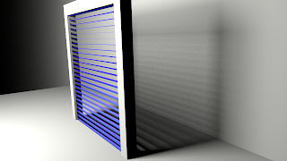
In the sample image and in the video we used this trick to render venetian blinds as seen from different position with just s single plane.
The concept is simple: the horizontal slats of the blinds appear taller when seen from an angle so we calculate the angle between the incidence vector and the x-axis (because unfortunately there is no attribute object:rotation to determine the up axis of an object) and divide that by maximum angle that would let us see something through the blinds. That fraction is used to paint part of a horizontal strip representing a slat. Finally we replace the shading normal by one that is perpendicular to the slat allowing for s bit of a curve across the slat:
surface venetianblinds(
  point Pos = P,
  float Spacing = 0.1,
  float Width = 0.1,
  float Curve = 0.2,
  
  output float Fac = 0,
  output float Top = 0,
  output normal Normal = N
){
  Top = dot(I,vector(0,0,1))>0;
  
  float maxangle = atan(Spacing/Width);
  float angle = abs(M_PI_2-acos(dot(normalize(-I),vector(0,0,1))));

  float height = Spacing;
  // TODO we should look at the sign here to prevent 'flip'
  if (angle < maxangle){ height *= angle/maxangle; }

  float z = mod(Pos[2],Spacing);
  Fac = (z < height);
  
  if(z< height){
    Normal = normalize(vector(0,0,1)+N*Curve*(height/2-z)/height);
  }
  
}

Example node setup

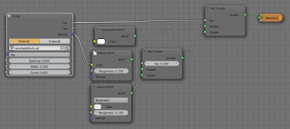
The node setup used to render both the still and the video looks like this: This material is applied to a simple plane. The lighting consists of a single mesh light on the left.
Rayleigh scattering in Cycles

Prompted by a question in a comment by Joakim Poromaa Helger I came up with this approach to emulate Rayleigh scattering (the effect that turns the sky blue and the sun red at the same time) in Cycles: by combining a transparent and a glass shader.


In the picture above there is a bright white sun on the right. In a material that exhibits Rayleigh scattering (like air) blue light is scattered more than red light. That means that light traveling from a lightsource through such material will be tinted red because blue light is scattered to all sides. In a direction away from the direct path of the light we see just this scattered blue light and not (or much less) the direct light.

Now if we combine a red(ish) transparent shader with a blue(ish) glass shader, the transparent shader will cause some of the light to be passed through the object without regard for index of refraction and give it a redish hue, while the glass shader will pass some (refracted) blue light through and reflect some. (In the sample picture I have turned off caustics because that takes forever to give a good quality render but also because in this setup caustics exhibit a blue color while it should be redish as well). The node setup looks like this:

With some extra trickery we can correct the color for any caustics as well:

(Note that this image took 10,000 samples and the caustics are still very noisy. Clearly caustics is not Cycles strong point. The light/shadow inside the orb are due to the fact I placed it slightly below the ground but am to lazy to fix it).

We achive the caustic coloring by arranging that the camera sees the blue glass shader while any object receiving diffuse light (like the floor) sees a red glass shader, a distinction we can make with help of the light path node:
Now obiously the effect here is exagerated for demonstration purposes and arguably it is not a real simulation of Rayleigh scattering but for artistic purposes this might be a good start.