A phong ramp (car paint?) OSL shader for Cycles

A phong ramp closure has been available for quite some time in Blenders OSL implementation (see the commit log) but this hasn't been exposed as a shader node yet. That is quite simple to do and in this post I present a bare bones implementation of such a shader node

I don't know much about car paint shaders, may be the reflection color changes as well with the view angle and not just the diffuse color but this might be a start for people wanting to implement such a fancy shader. This shader might be useful as well to implement soap bubble irridescence in a different way. (you might want to check the dicussion on Blender Artists).

surface phong_ramp(
 float Exp = 1,

 color C1=color(1,0,0),
 color C2=color(.8,.2,0),
 color C3=color(.6,0.4,0),
 color C4=color(.4,0.4,0.2),
 color C5=color(.2,0.4,0.4),
 color C6=color(0,0.4,0.6),
 color C7=color(0,0.2,0.8),
 color C8=color(0,0,1),
 
 output closure color Cout = 0
){
 color colors[8] = {C1,C2,C3,C4,C5,C6,C7,C8};
 Cout = phong_ramp(N, Exp, colors);
}
As you can see, all there is to this code is transfering the input values to the arguments of the built-in function. The function takes an array of eight colors so we have created eight input color sockets. I admit that it lacks elegance but it works.

Example node setup

the sphere in the example image was created with the following node setup:

A chainmail OSL shader in Blender Cycles

A golden oldie reimplemented in OSL: a simple 4-in-1 chainmail pattern.
If you want to know more about chainmail patterns, both historical and contemporary ones, you might like to visit artofchainmail.com or cgmaille.com.

In the picture ob the left I used the chainmail shader to generate the pattern on the neck flap. The picture was created with a wood texture from cgtextures.com for the table top but all other textures are procedural. The scene was lit using the Prov-Wash HDRI maps by Alex Hart as found on hdrlabs.com. I think it is a kind of museum and that fits the helmet setting nicely.
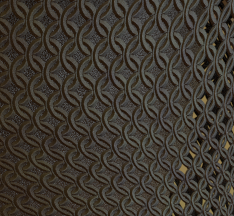
Like the barbwire and chainlink shaders the shader presented in this article is again essentially nothing more than a simple black and white pattern with the distance to the center of the line added as a feature to aid in generating bumps. The difficulty here is to get all those overlaps correct as can be seen in the enlarged cut out selection shown on the right.


#include "stdosl.h"

int between(float v, float a, float b){ return v >= a && v <= b; }
float arc(float r, float a, float b) { return sqrt(0.5-abs(0.5-((r-a)/(b-a)))); }
float rmap(float a, float b, float ra[3] ){
 if ( between(ra[0], a, b) ) { return ra[0]; }
 if ( between(ra[1], a, b) ) { return ra[1]; }
 if ( between(ra[2], a, b) ) { return ra[2]; }
 return -1;
}

float basepattern(float r1, float r2, float r3, int fx, int fy, float Rm, float Rp){
 float x0y0[3] = {r3, r1, r2};
 float x0y1[3] = {r2, r3, r1};
 float x1y0[3] = {r1, r3, r2};
 float x1y1[3] = {r2, r1, r3};
 
 float r = -1;
 if ( fx ){
  if ( fy ) {
   r = rmap(Rm, Rp, x1y1);
  } else {
   r = rmap(Rm, Rp, x1y0);
  }

 } else {
  if ( fy ) {
   r = rmap(Rm, Rp, x0y1);
  } else {
   r = rmap(Rm, Rp, x0y0); 
  }
 }
 return r;
}

shader chainmail4in1 (
 point Pos = P,
 float Scale = 1,
 float Radius = 0.47,
 float Width = 0.08,
 output float Fac = 0,
 output float Disp = 0
){
 point p = Pos * Scale ;
 float x = mod(p[0],1);
 float y = mod(p[1],1);
 
 float Rm = Radius - Width;
 float Rp = Radius + Width;
 
 float r=-1,r1,r2,r3,cr1,cr2,cr3;
 
 int fx = 0, fy = 0 , flip = y > x, flipt = y > ( 1 - x );
 if ( x > 0.5 ){ x = 1 - x ; fx = 1; }
 if ( y > 0.5 ){ y = 1 - y ; fy = 1; }
 
 r1 = hypot(x-0.5,y-0.5);
 r2 = hypot(x-0.5,y+0.5);
 r3 = hypot(x+0.5,y-0.5);
 
 float xc = mod(p[0]+0.5,1);
 float yc = mod(p[1]+0.5,1);
 
 int fxc = 0, fyc = 0, flipc = y > x;
 
 if ( xc > 0.5 ){ xc = 1 - xc ; fxc = 1; }
 if ( yc > 0.5 ){ yc = 1 - yc ; fyc = 1; }
 
 cr1 = hypot(xc-0.5,yc-0.5);
 cr2 = hypot(xc-0.5,yc+0.5);
 cr3 = hypot(xc+0.5,yc-0.5);

 if ( flip ^ flipt ){
  // base pattern
  r = basepattern(r1,r2,r3,fx,fy,Rm,Rp);
  if ( r> -1){
   Fac = 1;
   Disp = arc(r,Rm,Rp);
  } else {
   // connecting rings
   r = basepattern(cr1,cr2,cr3,fxc,fyc,Rm,Rp);
   if ( r> -1){
    Fac = 1;
    Disp = arc(r,Rm,Rp);
   }
  }
 } else {
  // connecting rings
  r = basepattern(cr1,cr2,cr3,fxc,fyc,Rm,Rp);
  if ( r> -1){
   Fac = 1;
   Disp = arc(r,Rm,Rp);
  } else {
   // base patterm
   r = basepattern(r1,r2,r3,fx,fy,Rm,Rp);
   if ( r> -1){
    Fac = 1;
    Disp = arc(r,Rm,Rp);
   }
  }
 }
}
The trick is to see that the pattern is very symmetrical. Each quadrant is basically the aame and consists of two quarter ring segments, one centered on the center of the square we are filling, the other one on the corner. The whole business of which to test for in what order is done to make sure that we know which ring segment is on top so that we can calculate a displacement correctly. It is all a bit too complicated to explain and in fact the code was created on a trial and error basis :-) It is however quite simple to use and that's why I share it of course :-)

Example node setup

Like most of the shaders I present on this blog the pattern probably is easiest to work with on an uv-mapped object. In the picture of the helmet the neckflap is just that, a curved, subdivided square that is uv-mapped with simple unwrapping. The node setup is shown below.
The green part is where we switch between a fully transparent shader or a metal shader based on the ouput of our script node. The diffuse part of the metal shader is given some color variation by the noise generated in the red box. The blue box s where we perturb our uv-coordinates a little bit adding a small amount of color noise in order to make our chainmail pattern a little less regular.

How to set up simple hdri environment lighting in Blender Cycles

In quite a few articles on this blog I present example images that use environment lighting and a detailed backplate. I found it not very intuitive at first to set up a scene in a way that gave me some control so I thought I'd share my findings here.

When using environment lighting with backplates you need of course have access to good resources and one of the best free resources I found is the sIBL Archive on hdrlabs.com. Each archive contains normally three images: a high resolution backplate, a low resolution hdri environment map and a high resolution hdri reflection map, all in a format that can be used by Blender directly. Just make sure you use an Environment Texture node (not a regular imaged texture). The environments we use here are all equilateral but Blender also has the option to use mirror ball images.

A high resolution (8000 x 4000 pixels) backplate is already huge and an hdri image is even bigger (typically 4 to 10 times) both because it uses more bits to store the information in each color channel and because it appears to compress less well. It would be wasteful to keep all this in memory if you don't need it because memory already is a precious commodity when rendering. Therefore each map has a different resolution: the backplate is very detailed, but is plain rgb, not hdri, and the environment map is very low resolution since you won't see it directly and lights don't need fine detail. In reflections however you might need some detail (if you have very shiny surfaces where you can see the environment) and in that case you might want to use the medium resolution reflection maps. In the image at the start of the article I used the low resolution enviroment map and as you can see the very glossy monkey on the right doesn't show a recognizable image in the reflection. In the image below we used a medium resolution reflection map which gives fair result while still being much smaller than an hdri map with the same resoltion as the back plate would be.

If we can see the background we have to create a setup for the world material nodes where we couple the highly detailed background image to the lower resolution environment or reflection map, in such a way that when we look a the background directly we see the backplate while in all other cases (like diffuse and specular reflection bounces for example) we use the hdri map. This is possible by using Cycles' light path node.

The light path node has an Is Camera Ray socket that will have a value of one if we are dealing with a camera ray and is zero otherwise. A camera ray is a ray that shoots directly from the camera so if our background is hit by a camera ray we present the high res backplate and in all other cases we present the hdri environment map. This is done by drivin the mix shader in the node setup above by this camera ray. Note that the backplate shader is the one that plugs into the lower input socket of the mix shader.

When you create your scene it is convenient to place your camera in the center, i.e. at location 0,0,0 because these environment images are shot like a panorama with the real world camera in its center. This doesn't have to be exact but in indoor scenes some distortion might be noticeable if you rotate the camera while it is not in the center.

Now if you want to change your view and lighting you could rotate the camera but then you would need to move all other objects as well. It might be much more convenient to rotate the background imagery. The backplate and the environment map will have to be linked of course to keep what you see and how things are lit in sync and the easiest way to do that is shown in the node setup below

The generated coordinates are fed through a vector mapping node before being connected to both background shaders. We now can rotate both images at the same time by changing the z-rotation value of the mapping node. (The other roatations are generally less useful as in these good quality pictures there is hardly ever the need to correct a tilted horizon for example but if need this could be done by rotating around the x or y axis).

A Hagelslag (sprinkles) OSL shader for Blender Cycles

Most of the noise patterns available in Blender are either continuous (like noise or musgrave) or serve a specific function (like voronoi or bands). None of these are easily adapted to generate the not quite microscopic dust particles that leave their marks in for example fingerprints. While developing such a shader I came across a great video by CGPGrey on Holland/The Netherlands, in which he mentions the national breakfast confectionery hagelslag (chocolate sprinkles). Because the shader we present here is easily adapted to generate sprinkle patters, I dubbed it the hagelslag shader, although originally I intended to present a picture of rod-like bacteria such as Bacillus subtilis, my guess is that people find this a tastier example.

The environment lighting and background plate in the picture is provided by HDRSource the Gold Room from HDRLabs.com. And yes I know the bread crust doesn't look tasty at all, that is why I always removed it as a child.
The code I presented earlier doesn't work on all version of the OSL compiler. The culprit was the return statement inside the actual shader definition. I think this is a bug in OSL , a return from a shader function should be possible, but I updated the code nevertheless. I tested it on Blender r53600 and r54202 on 64 bits Windows 7
The code below is self contained, which means I have included a replacement for the missing distance() function but I do not discuss that one here as I published a small blog article on it elsewhere.
The basic pattern is based on determining the distance to randomly scattered line segments. In its most pure form it might look like this:
The shader code is presented below and the inputs of the shader are (beside the position and scale) the number of sprinkles to produce per area (Np), a random Seed to vary the pattern, the Radius which controls the width of the sprinkle, and the Size which governs the length of the sprinkles. The output Fac is between 1 and 0, gradually reducing from centerline to edge.
#include "stdosl.h"

// replacement for the missing distance(p, p1, p2) function
float minimum_distance(point v, point w, point p) {
  vector s = w - v;
  float l2 = dot(s,s);
  if (l2 == 0.0) return distance(p, v);
  float t = dot(p - v, s) / l2;
  if (t < 0.0) return distance(p, v);
  else if (t > 1.0) return distance(p, w);
  vector projection = v + t * (s);
  return distance(p, projection);
}

shader sprinkles(
 point Pos = P,
 float Scale = 1,
 int Np = 1,
 int Seed = 42,
 float Radius = 0.05,
 float Size = 1,
 output float Fac = 0
){
 point p = Pos * Scale;
 point f = floor(p);
 
 int xx,yy,np;
 vector one = 1;
 
 for( xx=-1; xx<=1; xx++){
  for( yy=-1; yy<=1; yy++){
   point ff = f + vector(xx,yy,0);
   
   vector dp = vector(5,7,11);
   vector da = vector(5,3,1);
   vector dm = vector(7,5,2);
   
   for( np=0; np < Np; np++){
    vector pd1 = 2*cellnoise(ff+dp)-one;
    vector pd2 = 2*cellnoise(ff+dp+Seed)-one;
    
    dp += da;
 dp *= dm;
 dp = mod(dp,10000);
    
    point p1 = ff + pd1;
    point p2 = ff + pd2;
    
    p2 = (p2 - p1)*Size+p1;
    
    // reduce to 2D 
    p1[2]=0;
    p2[2]=0;
    p [2]=0;
    
    float r = minimum_distance(p1,p2,p);
    if ( r < Radius ) {
  //printf("%2.f %.2f\n",p,r);
     Fac = 1 - r/Radius;
    }
   }
  }
 }
}

Example node setup

The node setup for the plain pattern looks like this:
It uses a mix node that switches between two material based on whether Fac is larger than zero.
The shader node used for the image of the sandwich with the chocolate sprinkles is a variation on that:
Because the radius of a chocolate sprinkles varies a little bit along its length, we perturb the Radius with some noise (red box). The yellow box lets us switch between a completely transparent material and a chocolate material. (We use a transparent material here because we stacked two layers of sprinkles on top of each other, with different values for Seed to get a the effect of a thick layer of sprinkles. The green box converts the linear values of Fac to a rounded bump by calculating the sqaure root (power 0.5) and plugging it into a bump node. The brown box is our chocolate material, simply a dark brown but rather glossy material.

A replacement for the missing OSL distance to line segment function

The OSL implementation defines but apparently doesn't actually implement the three argument variant of the distance() function. In this short article I present a simple alternative.
While working on a new shader I noticed I got runtime errors that crashed Blender when I used the three argument variant of the distance() function to compute the shortest distance of a point to a line segment. I filed a bug report and although the Blender devs were very quick to verify and respond, the fact remains that it is a gap in the OSL libraries that won't be fixed by the Blender devs (although they have implemented a fix that will prevent Blender from crashing). That leaves us with the task of providing a workaround. Fortunately that is not too difficult.
Finding the shortest distance to a line segment is of course bssic geometry so it was easy enough to find numerous online resources. Based on those (references are in the code below) I came up with the following code:
#include "stdosl.h"

// replacement for the missing distance(p, p1, p2) function

// shortest distance to a line segment from p1 -> p2
// based on information from the following two sites:
// http://stackoverflow.com/questions/849211/shortest-distance-between-a-point-and-a-line-segment
// http://paulbourke.net/geometry/pointlineplane/

float minimum_distance(point v, point w, point p) {
  // Return minimum distance between line segment vw and point p
  vector s = w - v;
  float l2 = dot(s,s);
  if (l2 == 0.0) return distance(p, v);
  float t = dot(p - v, s) / l2;
  if (t < 0.0) return distance(p, v);
  else if (t > 1.0) return distance(p, w);
  vector projection = v + t * (s);
  return distance(p, projection);
}
I will not explain it here, refer to the sources mentioned in the code if you are interested, especially Paul Bourke's site is a treasure trove of useful information.

A fingerprint OSL shader for Blender Cycles

Scanning your own fingerprints for use in your renderings might not be such a good idea with new methods of identity theft being invented everyday so here I present a shader that generates random fingerprint patterns. Finally you can identify the suspect that emptied your whiskey glass!

In the example image we duplicated and separated a small square from the glass mesh and scaled it a minuscule bit outward, effectively turning it into a decal or sticker. This object was uv-mapped and the fingerprint material applied to it. (The decal is still a bit darker than the glass because I didn't use enough transparent bounces. I might update this image in the future.)

An elliptic mask shader

Besides the regular nodes this Cycles shader consist of two separate OSL shaders. The first is a generic one to generate elliptic masks, not unlike the one available in the compositor:
#include "stdosl.h"

shader ellipse(
 point Pos = P,
 point Center = 0.5,
 float Radius = 0.5,
 float E = 1,
 float Rotation = 0,
 float Blur = 0,
 output float Fac = 0
){
 point p = rotate(Pos,radians(Rotation),Center,Center+vector(0,0,1));
 vector d = p - Center;
 d[0] *= E;
 float r2 = d[0]*d[0]+d[1]*d[1];
 if (r2 <= Radius*Radius) {
  Fac = 1-Blur*sqrt(r2/(Radius*Radius));
 }
} 

Generating a flow field

The second one is a flow shader. It works by generating a number of points that are considered the centers of vortices (rotating vector fields) with different strengths. At the point being shaded all the vectors are summed and the magnitude of the resulting vector is calculated. This output is used in the example noodle at the end of this article as input to a sinus node to create the banding pattern. Of course this pattern only superficially resembles human fingerprints (for example, it will not produce whorls, just concentric circles) but it does resemble it and is in fact related to the way fingerprint patterns are produced in the developing embryo. Anyway, as always, shaders are not about science but about art. For more information check Wikipedia, this pdf or this research. The animation on that last site actually inspired me although I have no idea my simplistic implementation in any way resembles their approach apart from using a vector field to act as a base for generating the ridge patterns.
Apart from fingerprints I think it should be possible to generate all sorts of patterns that in real life might be produced by processes that resemble cellular automata or reaction-diffusion systems that are far too expensive to simulate insode a shader. Zebra stripes might be a prime example.
I think my approach is at generating these patterns for graphical purposes is quite new, but if you have pointers to similar solutions you saw elsewhere, please mention this is a comment.
#include "stdosl.h"
#include "node_texture.h"

shader flow(
 point Pos = P,
 float Scale = 1,
 int Np = 5,
 int Seed = 42,
 output float Fac = 0
){
 float da;
 point pa;
 float d;
 
 vector up   = vector(0,0,1);
 vector tdir = 0;
 
 int pi;
 
 for(pi=0; pi< Np; pi++){
  pa = Scale * point(
   cellnoise(point(pi,pi,pi)),
   cellnoise(point(pi,pi+Seed,pi)),
   cellnoise(point(pi,pi,pi+Seed)));
  da = pa[2];
  vector v = pa - Pos;
  float d = length(v);
  v[2]=0;
  v = normalize(v);
  tdir += cross(v,up)*da*d;
 }
 Fac = sqrt(dot(tdir,tdir));
}

If we use some lighting that shows of the details you can see that it resembles a fingerprint but is actually nowhere near a real one.

Example node setup

The are quite a few nodes in the example shown below, so it is good the understand the general flow. The flow shader is used drive a sinus node via a multiplication node that lets us control the spacing of the bands. The output of this sinus is only propagated if it is positive (that is what the greater than and multiply nodes do, akin to an electrical 'rectifier' circuit) [The red box]]. This is mutiplied (i.e. masked) by the output of the ellipse shader and again by some noise [both in the green box] before being fed into mixture of closures (shaders) that will turn complete transparent when black and whitish-with-a-slight-gloss if not black [the yellow highlight]. The sinusoidal ridges also drive the displacement, adding a little extra realism [the blue highlight].

A Barbwire OSL shader for Blender Cycles

The simple concept used to create a chain link fence is easily extended to a somewhat more elaborate shader that creates barbwire. Finally we can keep the farm animals out of our rendered gardens (but as a goat owner myself I do not really think you should use barbwire to keep animals out except for humans :-)

I won't claim that the composite is very good, but the barbwire material itself holds up quite well even fairly close up.
In the example image I used the sIBL HDRI set 'Topanga Forest B' from Blochi as found on the sIBL archive and for the wooden posts some textures from CGTextures.
The code for the shader is pretty tangled, mainly because the spikey bit of the barbwire is pretty hard to code. The Xscale input is provided in order to make it possible to reduce the number of spikes per length of wire. By default we generate one spike per two turns. If you want to reduce this, you increase the number of turns, scale your input position in the x-direction and divide the Xscale input by the same amount (otherwise the turns on the spike would scale along and look way to thick).
#include "stdosl.h"

float arc(float r){ return sqrt(0.25-(r-0.5)*(r-0.5)); }

shader barbwire(
 float Width = 0.05,
 int Turns = 2,
 int Spiketurns = 2,
 float Xscale = 1,
 point Pos = P,
 output float Fac = 0,
 output float Displ = 0
){
 float x = mod(Pos[0],1);
 float y = mod(Pos[1],1);
 
 if ( x > 0.5 ) {
  x = 1 - x;
  y = 1 - y;
 }
 
 float w = Width/2;
 float t = M_2PI*x*Turns;
 
 float c = cos(t);
 float h = c*w+w;
 float l = c*w-w;
 
 y -= 0.5;
 // the barb part
 float BWidth = Width*Xscale;
 float Lw = BWidth*(Spiketurns-1);
 float Hw = BWidth*Spiketurns;
 if ( x > Lw && x < Hw && y > 1.5*Width && y<4 br="" idth="" part="" spikey="" the="">  if( y<3 br="" idth="" x-width="" y-3="">   Fac = 1;
   Displ = arc(mod(x,BWidth)/BWidth);
  }
 } else if ( x < Hw && abs(y) < 2*Width ){
  if ( abs(y) > 1.5*Width) { // the rounded top and bottom parts
   if ( abs(y) - 1.5*Width < w*arc(mod(x,BWidth)/BWidth) ){
    Fac = 1;
    Displ = arc(mod(x,BWidth)/BWidth);
   }
  } else { // the main part
   Fac = 1;
   Displ = arc(mod(x,BWidth)/BWidth);
  }
 }
 // the wire part 
 else {
  // alternating top/bottom checks to get correct crossings
  if ( (int)(t/M_PI) % 2 == 1 ){
  
   if ( y > l && y < h ) {
    Fac = 1;
    Displ = arc((y-l)/Width);
   } else if ( -y > l && -y < h ) {
    Fac = 1;
    Displ = arc((-y-l)/Width);
   }
   
  } else {
  
   if ( -y > l && -y < h ) {
    Fac = 1;
    Displ = arc((-y-l)/Width);
   } else if ( y > l && y < h ) {
    Fac = 1;
    Displ = arc((y-l)/Width);
   }
  }
 }
}

Example node setup

In the example image at the start of this article the lengths of barbwire were modelled by creating a single square, uv-unwrapping it and then adding an array modifier and a curve modifier to this square. This way we could edit the curve anyway we liked while the square repeats itself as many times as necessary (I set the length of the array modifier to the the length of the same curve that was used in the curve modifier). The noodle that applies the barbwire segment to the square looks like this (it is basically the same as the one for the chain link fence shader):

A 4D voronoi OSL shader for Blender Cycles

I took a post on Blender Artists as a challenge and created a 4D voronoi shader.

Blogspot won't show animated gifs but I put up a short sequence on PasteAll and if that doesn't work it is also on my site. In this animated gif, the fourth dimension (time) is animated from 0 to 1 in 50 frames.
The shader presented below is simple enough but convoluted because we cannot manipulate arrays like points or vectors in OSL but otherwise it is a straight forward extension of Blenders bundled voronoi implementation, especially because OSLs cellnoise function supports 4D noise out of the box (you can pass it a point and a float).
#include "stdosl.h"

void cellnoise_color4d(float p[4], float c[4])
{
 c[0] = cellnoise(point(p[0],p[1],p[2]),p[3]);
 c[1] = cellnoise(point(p[1],p[0],p[2]),p[3]);
 c[2] = cellnoise(point(p[1],p[2],p[0]),p[3]);
 c[3] = cellnoise(point(p[3],p[1],p[2]),p[0]);
}

/* Voronoi 4D . we always use distance squared as the distance metric */

void voronoi4d(point p, float t, float da[4], point pa[4], float ta[4])
{
 /* returns distances in da, point coords in pa and time coords in ta*/
 int xx, yy, zz, tt, xi, yi, zi, ti;

 float op[4] = {p[0],p[1],p[2],t};
 
 xi = (int)floor(p[0]);
 yi = (int)floor(p[1]);
 zi = (int)floor(p[2]);
 ti = (int)floor(t);

 da[0] = 1e10;
 da[1] = 1e10;
 da[2] = 1e10;
 da[3] = 1e10;

 for (xx = xi - 1; xx <= xi + 1; xx++) {
  for (yy = yi - 1; yy <= yi + 1; yy++) {
   for (zz = zi - 1; zz <= zi + 1; zz++) {
    for (tt = ti - 1; tt <= ti + 1; tt++) {
     float ip[4] = {xx, yy, zz, tt};
     float vp[4];
     cellnoise_color4d(ip,vp);
     float pd[4] = { op[0] - (vp[0] + ip[0]), 
         op[1] - (vp[1] + ip[1]),
         op[2] - (vp[2] + ip[2]),
         op[3] - (vp[3] + ip[3])};
     // always distance squared
     float d = pd[0]*pd[0]+pd[1]*pd[1]+pd[2]*pd[2]+pd[3]*pd[3];

     vp[0] += xx;
     vp[1] += yy;
     vp[2] += zz;
     vp[3] += tt;

     if (d < da[0]) {
      da[3] = da[2];
      da[2] = da[1];
      da[1] = da[0];
      da[0] = d;

      pa[3] = pa[2]; ta[3] = ta[2];
      pa[2] = pa[1]; ta[2] = ta[1];
      pa[1] = pa[0]; ta[1] = ta[0];
      pa[0] = point(vp[0],vp[1],vp[2]); ta[0] = vp[3];
     }
     else if (d < da[1]) {
      da[3] = da[2];
      da[2] = da[1];
      da[1] = d;

      pa[3] = pa[2]; ta[3] = ta[2];
      pa[2] = pa[1]; ta[2] = ta[1];
      pa[1] = point(vp[0],vp[1],vp[2]); ta[1] = vp[3];
     }
     else if (d < da[2]) {
      da[3] = da[2];
      da[2] = d;

      pa[3] = pa[2]; ta[3] = ta[2];
      pa[2] = point(vp[0],vp[1],vp[2]); ta[2] = vp[3];
     }
     else if (d < da[3]) {
      da[3] = d;
      pa[3] = point(vp[0],vp[1],vp[2]); ta[3] = vp[3];
     }
    }
   }
  }
 }
}

shader node_voronoi_texture(
 float Scale = 5.0,
 point Vector = P,
 float Time = 0,
 output float Fac = 0.0,
 output color Color = color(0.0, 0.0, 0.0))
{
 point p = Vector;

 /* compute distance and point coordinate of 4 nearest neighbours */
 float da[4];
 point pa[4];
 float ta[4];
 
 voronoi4d(p * Scale, Time * Scale, da, pa, ta);

 Fac = fabs(da[0]);
 Color = color(Fac);
}

Example node setup

Straight forward enough but note the keyframed Time value.

A Chainlink Fence OSL Shader for Blender Cycles

A simple shader to generate a chain link fence pattern that shows that a little displacement can go a long way.

The example image was again generated using one of Bob Groothuis excellent HDRI maps from his Dutch Skies collection. The concrete texture in the front is from www.cgtextures.com

The whole trick in generating a chain link fence pattern is realizing there is a lot of symmetry involved so we only need to think about the calculations for one part.


#include "stdosl.h"

float arc(float x){ return sqrt(1-(x-0.5)*(x-0.5)/0.25); }

shader chainlink(
point Pos = P,
float Width = 0.05,
output float Fac = 0,
output float Displ = 0
){
float x = mod(Pos[0],1);
float y = mod(Pos[1],1);
float ox = x ;
float oy = y ;
x += Width * (0.5 - oy );
y -= Width * (ox - 0.5 );
if ( y > 0.5 ){
y = 1 - y;
x = 1 - x;
}
if ( x > 0.5 ){
if ( y > 0.5 - Width ){
Fac = 1;
Displ = arc((y-(0.5-Width))/Width);
}else if (x < 0.5 + Width) {
Fac = 1;
Displ = arc((x-0.5)/Width);
}
}else{
float r = hypot(x-0.5,y-0.5);
if (r < Width) {
Fac = 1;
Displ = arc(r/Width);
}
}
}
The symmetry trick is in lines 17 - 20 where we invert the right half of a square around the center. The way we generate our pattern would cause the ends of the wires at the edges of the square not to line up so in line 15 an 16 we skew the grid a bit to correct this. this extra work before hand makes generating the wires of the chain link fence now very straight forward,

Example node setup

The way to use this shader is by using a default (aka reset) uv map from a simple plane and scale/rotate it as you see fit. The node setup shown here is about the simplest you can get: we simply map the Fac socket to a mix shader to map between a fully transparent shader and a material, in this cas a node group that implements some simple rather dull metal (not shown here). The caclculated displacement is directly plugged into the material output node and thereby converted to a surface normal but we could have used a bump node as well.

Note that although hardly visible in the ambient lighting of the example image, our material does cast nice shadows.

A rainbow OSL shader for Blender Cycles

Here I present an OSL shader to render a simple, single rainbow in a scene.

The example image was generated using one of Bob Groothuis excellent HDRI maps from his Dutch Skies collection.
The aim here is to produce a believable but not necessarily completely realistic rendition of a rainbow. The theory behind rainbows is quite clear but we don't want to go as far as approximating Mie theory as this makes for very complex shaders indeed.
So what do we consider believable? The color progression and the angle of the arc should be correct of course but also we would like to be able to influence the intensity. Rainbows are most often seen against the backdrop of rain showers and the density of the distribution of the raindrops is not uniform and this has an effect on the visibility of the rainbow.

OSL limitations

In real life rainbows are seen when there is a very bright light behind you, most often the sun. The center of the rainbow arc is positioned in the direction of your shadow. Now we want to project the rainbow on a plane we can use a trick to find out the camera vector (by transforming the location of the object from world to camera space, see line 16 below) but there is currently no way to find out the location of objects other than the one being shaded. That means that to create a believable scene we must take care ourselves to position the plane with the rainbow opposite the sun, relative to the camera!
Another thing I found that although OSL has a wavelenght_oolor() function it was very difficult to create the washed out colors that we associate with rainbows. So instead of trying to mix colors and account for exact dispersion and stuff like the size of the disk of the sun, I opted for just calculating the angle an plugging the result into a color ramp.

#define INNER 0.766   // cos(40)
#define OUTER 0.743   // cos(42)
#define SPREAD (INNER - OUTER)

shader rainbow(
 output float T = 0 
){
    if( raytype("camera") ){
        point Pos = P;
     // vector from point being shaded to camera
        point cam = normalize(transform("common","camera",Pos));

        // vector from object center to camera
        point obj;
        getattribute("object:location",obj);
        obj=transform("world","camera",obj);
    
        obj=normalize(obj);
        
        float theta = dot(obj,cam);
     if (theta > OUTER && theta < INNER){
            theta = (theta-OUTER)/SPREAD ;
            T = theta;
    }
    }
}
So basically all that this shader does, is calculating the cosine of the angle between the vector pointing from the camera to the point being shaded and the vector pointing from the camera to the center of the object being shaded (line 20).

Example node setup


The trick used to create the example image is to multiply a suitable density (here a simple vertical gradient mapped to an appropriate position, shown on the left) to the the output color that we extract from a color ramp and input that into a diffuse shader that is added (not mixed) to a completely transparent shader. Note that the color ramp must start with an all black node (because T is zero outside the rainbow). The plane to which this material is added may be positioned at any distance from the camera so it is possible for example to position buildings that partially obscure the rainbow.

A Fabric OSL shader for Blender Cycles

In this post I present a simple shader that creates fabric or weave patterns.
The shader that is shown in the code below is not only capable of creating simple over-under patterns but also so called twill patterns. Its application is of course not limited to just fabrics, you could use it for baskets made of spliced bamboo for example or a divider made of hazel twigs.

The code for the shader is as often quite simple:
// greatest common divisor
int gcd(int A, int B){
    int a=A, b=B;
    if (a == 0) { return b; }
    while (b != 0) {
        if (a > b) {
            a = a - b;
        } else {
            b = b - a;
        }
    }
 return a;
}

// smallest common multiple (assumes a, b > 0 )
int scm(int a, int b){ return a*b/gcd(a,b); }

shader weave(
 color WarpColor = color(0.8,0,0),
 color WeftColor = color(0,0.8,0),
 int skip = 1,
 int underrun = 1,
 int overrun = 1,
        float WarpWidth = 0.8,
        float WeftWidth = 0.8,
 vector Coordinates = 0,
 output color Color = 0,
 output int Index = 0,
        output float Dist = 0
)
{
 int ny = underrun + overrun;
 int nx = scm(skip,ny);
 
 float x = mod(Coordinates[0],1.0);
 float y = mod(Coordinates[1],1.0);
 
 int ix = int(floor(x*nx));
 int iy = int(floor(y*ny));

        float cx = mod(x*nx,1.0);
        float cy = mod(y*ny,1.0);
     
 int top;
 top = ((iy+skip*ix)%ny) < overrun;

        float lx = (1-WarpWidth)/2;
        float hx = 1-lx;
    float ly = (1-WeftWidth)/2;
    float hy = 1-lx;

    if (top) {
        if ( cx > lx && cx < hx ){
            Index = 1;
            Color = WarpColor;
            Dist = abs(0.5-cx);
        } else if (cy > ly && cy < hy ){
            Index = 2;
            Color = WeftColor;
            Dist = abs(0.5-cy);
        }
    } else {
        if (cy > ly && cy < hy ){
            Index = 2;
            Color = WeftColor;
            Dist = abs(0.5-cy);
        } else if ( cx > lx && cx < hx ){
            Index = 1;
            Color = WarpColor;
            Dist = abs(0.5-cx);
        }
    }    
}
You may experiment with the skip, overrun and underrun values to get different patterns. The only real trick is to determine if we should display the vertical thread on top or the horizontal one. This is done in line 45. The rest of the code then simply checks whether we are withing the width of a thread.

Example node setup

The shader may be straightforward, the node setup used to create a canvas (or burlap) like appearance is less so because we need to introduce a certain amount of color variation inside the individual fibres and make sure that we have transparency in between the fibres (click to enlarge):

Future steps

As I am convinced Blender could benefit from an extensive set of very basic patterns that can be reused, I think I'll focus on a polkadot pattern for a next article.